< Previous   Next >

2008 - MX-5 - Brakes

DTC C1279, C1280, C1281, C1282, C1951, C1952, C1959, C2768 [DYNAMIC STABILITY CONTROL (DSC)]


DTC

C1279, C1280, C1281, C1282, C1951, C1952, C1959, C2768

Combined sensor system

DETECTION CONDITION

  • C1279

    • The yaw rate value from the combined sensor (yaw rate part) exceeds specification while the vehicle is stopped or while accelerating from a standstill.

  • C1280

    • The difference between the yaw rate value calculated by each sensor and the yaw rate value from the combined sensor (yaw rate part) exceeds specification.

  • C1281

    • The difference between the lateral-G value calculated by each sensor and the lateral-G value from the combined sensor (lateral-G part) exceeds specification.

  • C1282

    • Specified signal pattern from combined sensor has not output after the ignition switch is turned to the ON position.

  • C1951

    • The monitor voltage from the combined sensor (lateral-G part) is not within specification.

  • C1952

    • The monitor voltage from the combined sensor (yaw rate part) is not within specification.

  • C1959

    • The lateral-G value from the combined sensor (lateral-G part) exceeds specification.

  • C2768

    • There is an abnormality in the signal from the combined sensor (yaw rate part).

POSSIBLE CAUSE

  • Open circuit in the wiring harness between ignition switch and combined sensor terminal E or short circuit to ground

  • Open circuit in the wiring harness between DSC HU/CM terminal Y and combined sensor terminal F or short circuit to ground

  • Open circuit in the wiring harness between DSC HU/CM terminal AB and combined sensor terminal C or short circuit to ground

  • Open circuit in the wiring harness between DSC HU/CM terminal AE and combined sensor terminal A or short circuit to ground

  • Open circuit in the wiring harness between DSC HU/CM terminal AA and combined sensor terminal B or short circuit to ground

  • Open circuit in the wiring harness between DSC HU/CM terminal AI and combined sensor terminal D

  • Combined sensor malfunction

  • Poor connection at connectors (female terminal)


Diagnostic procedure

STEP

INSPECTION

ACTION

1

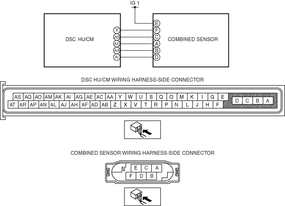
INSPECT COMBINED SENSOR POWER SUPPLY FOR OPEN CIRCUIT
  • Turn the ignition switch to the ON position (engine off).

  • Measure voltage between combined sensor terminal E (harness-side) and ground.

  • Is the voltage B+?

Yes

Go to the next step.

No

Repair or replace the wiring harness for open circuit between combined sensor terminal E and ignition switch, then go to Step 12.

2

INSPECT COMBINED SENSOR GROUND FOR OPEN CIRCUIT
  • Turn the ignition switch off.

  • Disconnect DSC HU/CM and combined sensor connectors.

  • Inspect for continuity between DSC HU/CM terminal Y (harness-side) and combined sensor terminal F (harness-side).

  • Is there continuity?

Yes

Go to the next step.

No

Repair or replace the wiring harness for open circuit between DSC HU/CM terminal Y and combined sensor terminal F, then go to Step 12.

3

INSPECT COMBINED SENSOR (YAW RATE PART) SIGNAL FOR OPEN CIRCUIT
  • Inspect for continuity between DSC HU/CM terminal AA (harness-side) and combined sensor terminal B (harness-side).

  • Is there continuity?

Yes

Go to the next step.

No

Repair or replace the wiring harness for open circuit between DSC HU/CM terminal AA and combined sensor terminal B, then go to Step 12.

4

INSPECT COMBINED SENSOR (YAW RATE PART) SIGNAL FOR SHORT TO GROUND
  • Turn the ignition switch off.

  • Inspect for continuity between DSC HU/CM terminal AA (harness-side) and ground.

  • Is there continuity?

Yes

Repair or replace the wiring harness for short to ground between DSC HU/CM terminal AA and combined sensor terminal B, then go to Step 12.

No

Go to the next step.

5

INSPECT COMBINED SENSOR (LATERAL-G PART) SIGNAL FOR OPEN CIRCUIT
  • Inspect for continuity between DSC HU/CM terminal AI (harness-side) and combined sensor terminal D (harness-side).

  • Is there continuity?

Yes

Go to the next step.

No

Repair or replace the wiring harness for open circuit between DSC HU/CM terminal AI and combined sensor terminal D, then go to Step 12.

6

INSPECT COMBINED SENSOR (LATERAL-G PART) SIGNAL FOR SHORT TO GROUND
  • Turn the ignition switch off.

  • Inspect for continuity between DSC HU/CM terminal AI (harness-side) and ground.

  • Is there continuity?

Yes

Repair or replace the wiring harness for short to ground between DSC HU/CM terminal AI and combined sensor terminal D, then go to Step 12.

No

Go to the next step.

7

INSPECT REFERENCE SIGNAL FOR OPEN CIRCUIT
  • Turn the ignition switch off.

  • Inspect for continuity between DSC HU/CM terminal AE (harness-side) and combined sensor terminal A (harness-side).

  • Is there continuity?

Yes

Go to the next step.

No

Repair or replace the wiring harness for open circuit between DSC HU/CM terminal AE and combined sensor terminal A, then go to Step 12.

8

INSPECT REFERENCE SIGNAL FOR SHORT TO GROUND
  • Turn the ignition switch off.

  • Inspect for continuity between DSC HU/CM terminal AE (harness-side) and ground.

  • Is there continuity?

Yes

Repair or replace the wiring harness for short to ground between DSC HU/CM terminal AE and combined sensor terminal A, then go to Step 12.

No

Go to the next step.

9

INSPECT TEST SIGNAL FOR OPEN CIRCUIT
  • Turn the ignition switch off.

  • Inspect for continuity between DSC HU/CM terminal AB (harness-side) and combined sensor terminal C (harness-side).

  • Is there continuity?

Yes

Go to the next step.

No

Repair or replace the wiring harness for open circuit between DSC HU/CM terminal AB and combined sensor terminal C, then go to Step 12.

10

INSPECT TEST SIGNAL FOR SHORT TO GROUND
  • Turn the ignition switch off.

  • Inspect for continuity between DSC HU/CM terminal AB (harness-side) and ground.

  • Is there continuity?

Yes

Repair or replace the wiring harness for short to ground between DSC HU/CM terminal AB and combined sensor terminal C, then go to Step 12.

No

Go to the next step.

11

INSPECT COMBINED SENSOR

Yes

Go to the next step.

No

Replace the combined sensor, then go to the next step.

(See COMBINED SENSOR REMOVAL/INSTALLATION.)

12

VERIFY DTC TROUBLESHOOTING COMPLETED.

Yes

Replace the DSC HU/CM, then go to the next step.

(See DSC HU/CM REMOVAL/INSTALLATION.)

No

Go to the next step.

13

VERIFY AFTER REPAIR PROCEDURE.
  • Are any other DTCs present?

Yes

Go to the applicable DTC inspection.

(See ON-BOARD DIAGNOSIS[DYNAMIC STABILITY CONTROL (DSC)].)

No

DTC troubleshooting completed.


< Previous   Next >
Back to Top
© 2012 Mazda North American Operations, U.S.A.