2008 - MX-5 - Engine
ACCELERATOR PEDAL POSITION (APP) SENSOR INSPECTION [LF]
NOTE:
Before performing the following inspection, make sure to follow the procedure as indicated in the troubleshooting flowchart. (See HOW TO USE THIS MANUAL.)
1. Connect the M-MDS to the DLC‐2.

2. Turn the ignition switch to the ON position.
3. Select APP1 and APP2 PID on the M-MDS.
4. Verify that the APP1 and APP2 PID is within the specification when the accelerator pedal not depressed. (See PCM INSPECTION [LF].)
Circuit Open/Short Inspection
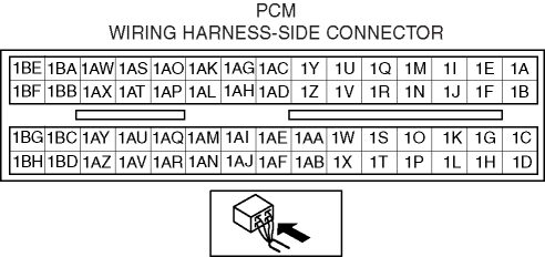
1. Disconnect the PCM connector. (See PCM REMOVAL/INSTALLATION [LF].)
2. Disconnect the APP sensor connector.
3. Inspect the following wiring harnesses for an open or short circuit. (Continuity inspection)

Open circuit
If there is no continuity in the following wiring harnesses, there is an open circuit. Repair or replace the wiring harness.
APP sensor terminal A and PCM terminal 1AJ
APP sensor terminal B and PCM terminal 1AV
APP sensor terminal C and PCM terminal 1AP
APP sensor terminal D and PCM terminal 1AL
APP sensor terminal E and PCM terminal 1AS
APP sensor terminal F and PCM terminal 1AO
Short circuit
If there is continuity in the following wiring harnesses, there is a short circuit. Repair or replace the wiring harness.
APP sensor terminal A and body ground
APP sensor terminal B and power supply
APP sensor terminal C and body ground
APP sensor terminal C and power supply
APP sensor terminal D and body ground
APP sensor terminal E and power supply
APP sensor terminal F and body ground
APP sensor terminal F and power supply
< Previous Next >